
Introduction
I was making good progress on the toy kitchen last fall, and then my son Eliot was born a month too soon, and we moved to a new house that same week. It was some time before I was at leisure to revisit the project (long after the contest was over) and it looks like the OLED screen (which had always been rather flaky) was no longer functioning at all.
I had still hoped to make something of the Grove Toy Kit and submit some step-by-step instructions for it, since the folks at Seeed so very kindly sent me the kit. At work recently, I finally received authorization to install Linux on my main workstation, but there have been a few things that I have wanted:
- I wanted an easy way to lock my screen when I got up. Windows had WIN+L, and I hadn’t bothered finding the Linux equivalent key combination.
- I wanted an easy way to control my music player. I use MPD and Sonata, and frequently have to pause or adjust the volume when someone comes by to consult me.
- I wanted a better notification for my Pidgin IM client. The default (as far as I could find it) merely changed the color of the chat window’s entry in the system bar, but it didn’t stand out enough for me to notice it in a timely manner. My mis-configuration of MPD prevented any aural notifications from working, so I was quickly getting rather unresponsive to IMs, which annoyed my teammates. I fixed the MPD configuration, but still wanted additional notification (if, say, I wasn’t wearing my headphones).
Design Notes

A front view of the controller in its classy enclosure, with four touch sensor buttons, a potentiometer, and an RGB LED (on the side). The leftmost button is "previous track", the left-center is "pause/resume", the right-center is "next track" and the rightmost is "pause and lock screen".
I decided to build a stand-alone controller for MPD, something that would use a serial interface to a bunch of buttons and a knob, and maybe an LED for status. I had (almost) everything I needed in the Grove Kit: Seeeduino, Grove Base Shield, Chainable RGB LED, and an I2C Touch Sensor, along with a bunch of cables. I had to roll my own Potentiometer, but that wasn’t too tricky.
The thing I like most about the Grove system is that it is pretty easy to assemble the hardware in a meaningful configuration in short order. If Seeed would package up a solid Arduino utility library for their various sensors, it would be even more powerful. As it was, I had to cobble together the software myself. I was able to re-use the touch sensor library I made from my earlier work on the kitchen project. I had to implement my own interface to the RGB LED (based on some examples they gave). I will be posting the source for the whole project, but I may try and package that up as more of a standalone library.
Anyway, here are some step-by-step instructions for the project.
Electronics

A top view. It's crowded in there! Note the classy twist-tie mounting mechanism. Also note the homebrew potentiometer plug, wired in on the right, and insulated with heat-shrink. On the lower-left is the I2C touch controller board.
- Construct the potentiometer twig:
- Take a spare Grove cable and cut it in two (save the spare, you can make something else out of it).
- Solder one side of the pot to VCC (red), the other side to ground (black), and the center tap to either of the data wires (yellow or white). The data line you pick just determines which of the two inputs the pot goes to, but you can also pick which socket on the shield you use, so it doesn’t matter a whole lot.
- Put it all together:
- Connect the I2C Touch Sensor to one of the I2C ports (Note: this makes A4 and A5 unavailable for other purposes).
- Connect the potentiometer you made to one of the other analog inputs (say, A0 or A1).
- Connect the RGB LED to one of the unused digital ports (Note: D0 and D1 will be used by the serial connection. I chose D12 and D13)
- Plug the shield into your Arduino (or Seeeduino, or other device with a compatible form factor).
Software
I’m afraid the software is rather unwieldy to include inline here. In the github repo, you’ll find the main sketch as ‘mpd_control_panel.pde’, which puts together the MPR121 interface library (included) and the control for reading the pot and activating the LED. I hope it’s relatively self-explanatory (though it probably needs some cleanup).
Enclosure

A better view of the back, showing more twist-tie mounting connectors. The whole system is weighty enough that, combined with the sensitivity of the touch sensors, it will not slide on the desk under the touch required to activate an input button.
For the enclosure, I used a sturdy cardboard box I had that was about the right size (though I had to hang the LED off the side). I wanted something that I could possibly mount to the bottom of the desk, right at the edge, to keep the desk surface clear. Cardboard was pretty easy to cut out and mount things to, and seems sturdy enough for my purposes. I had to cut extra stuff out around the top of the touch sensor buttons, because of the glue holding the sensor wires in place. Some masking tape on the back helps hold the buttons in place.
I don’t have a photo from the correct angle, but there’s a small cutout on the left for the USB cable, which will allow the system to be connected to the PC for the serial interface.
Interface
The PC interface is a Python script that communicates over the FTDI USB serial port provided by the Seeeduino. It uses the mpc command-line client for the MPD server. The command protocol is as simple as it can get:
T# (for # = 0-F): Current status of the touch sensor buttons, as a 4 bit int, with the LSB representing the leftmost button, sent on change. Note that 0 means no buttons are touched, I’m not using this at the moment, but may someday.
A# – A###: The current volume level, from 0 to 100, sent on change. This was actually a bit on the noisy side, so I’d get events from time to time. I might lower the sensitivity and only send even numbers, if it proves to be annoying
L######: Set the LED to the given hex RRGGBB color. The total latency from the PC to the LED is pretty bad, so you can’t really use this sequence to do cool, fast color changes. I have considered using a built-in set of various fading programs, but haven’t gotten around to it.
The python script itself listens for Serial events, and invokes the corresponding commands. When a command is successfully received, it lights the LED green for 1 second. To allow the separate Pidgin notifier script to work, I added a UDP socket listener. When a new IM is received, the IM notifier sends a message on that socket, and when the control script receives it, it turns the LED blue for 1 second. I tried making it robust to unplugging and replugging the control panel in (so it could always just be running in the background), but it appears that if I am trying to access /dev/ttyUSB0 with the script and plug the device in, it enumerates as /dev/ttyUSB1. I don’t want to bother making the script try and detect this, so for now, I think I will just force a restart. Now that I’m done taking photos, I see little reason to disconnect it.
This all sounds complicated, but it really wasn’t too bad. Here’s the python script for the notifier (latest version available in the github repo):
The python script for the MPD console controller itself is available in the github repo, as ‘mpd_control.py’. It starts a threaded UDP server in the background (to listen for IM notification commands) and then listens on the Seeeduino’s serial interface for commands in the protocol language.
There is a separate script for listening to the Pidgin IM client protocol for new message notification, called ‘pidgin_notifier.py’. When there’s a new message to a window that is not in the foreground, it opens a UDP connection to the controller and sends a few bytes, which causes the controller script to trigger the LED notification.
Conclusion
It could hardly have been easier to assemble this thing. I had it in one piece, enclosure and all, in less than an hour. I implemented the basic button software in an hour, another 30 minutes for the volume control, and another hour for the LED. The Python interface was another 15-20 minutes.
 The other part of the oven control panel is the

 , which is way too much. If I up the heat sink size to 12″x6″, I get
  , which is not as awesome, but is probably doable. I’ve updated the analysis to reflect all of this.]
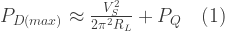
 is the maximum power dissipation
 is the total power supply voltage (in this case, for the Squelette, ±18V = 36V)
 is the load resistance (in this case, 8Ω impedance speakers)
 is the quiescent power dissipation of the device
 is the total thermal resistance from the junction to ambient, the sum of
 (junction to case) (listed in the datasheet as 2 oC/W)
 (case to heat-sink, e.g., the thermal resistance of your insulating pad or thermal compound layer) (in my case, the insulating pads are claimed 0.33 oC/W
 (heat sink to ambient) (this is what we’re trying to determine)
 is the maximum junction temperature from the datasheet (listed as 150 oC)
 is the maximum ambient temperature at which we are planning to operate the device (for example, 70 oC)
 .
.


 (see note (2))
 is the heat transferred per unit time
  is the heat transfer area of the surface (m2)
 is the
  is the temperature difference between the surface and the bulk fluid (K or oC)


 of 4.3 oC/W.


 limit of 4.33 oC/W (from (2b)), it looks like we won’t be able to run quite at 70oC ambient temperature. If our total thermal resistance with this heatsink is 2 + 0.33 + 4.8 = 7.1 oC/W, we can see that at an ambient temperature of 20 oC, dissipating 12 W of power, our junction temperature should be:


 , but also because most datasheets I have seen do not provide the dimensions of the die itself. Using the reduced dimensions results in a value of ~0.8 oC / W, rather than ~0.5 oC / W. That seems relatively insignificant to me, but I’m certainly open to other feedback on the matter.


